1996 Dodge Neon SOHC: ATX to MTX swap
*****DISCLAIMER*****
I am not responsible for personal injury or damage to your vehicle. I have personally written this document with safety as a priority and have performed all the procedures verbatim and successfully swapped a ATX neon to a MTX. Personal skill level is relative and if you do not feel confident in performing an operation such as this “swap” procedure, I would not recommend performing this procedure until you posses a higher skill level. You are not incapable it just takes time to develop the skill and confidence by performing less demanding tasks and building up to larger ones such as a transaxle swap or forced air induction upgrade, etc. No matter how experienced you are there is always an element of risk that you should be aware of.
ATX - automatic transaxle
MTX - manual or standard shift transaxle
Acknowledgements
Jerry and his son Corey who sold me 90% of the parts needed for the swap, all of which were in GREAT condition!
My girlfriend Lauren - For helping install the MTX and for lunch and dinner everyday of the swap
My roomate Rusty - for helping align the MTX
My good friend Jessika - for helping install the MTX and dinner
<neons.org The user may have further questions regarding the swap, this link will take you to the specific transmission swap discussion board on the neons.org forum. Feel free to give a shoutout for a successful transmission swap!
<www.modernperformance.com for the MTX transaxle fluid and other parts
<www.msu.edu/~lareseer/trannySwap.html for being one of the earliest to build a Dodge Neon transaxle swap website
<www.allpar.com/neon/clutch.html for having an excellent discussion on a MTX clutch installation
<www.haynes.com for having a thorough repair manual which provides the majority of the steps to perform the swap
<dodgeforum.com for being a great forum and resource
"COMMENTARY"
“READ EVERYTHING TWICE! When reading the figures note that Fig 1 simply corresponds to the figure in the webpage. Figure numbers in parenthesis (11.28.1) correspond to a similar figure found in the Haynes Repair Manual, the 11 stands for chapter number, the 28 stands for section number and the 1 stands for the figure number. Only some similarly taken pictures are provided by me in this online manual. It is HIGHLY recommended to purchase the Haynes Repair Manual in order to reference other figures. This is especially important when performing the clutch installation. Personally, I did not take that many pictures of the clutch install but there are more extensive pictures in the Haynes Repair Manual. Also, found in the clutch install section is a link to Allpar's website that shows two individuals who exclusively did a clutch install for a neon. I highly recommend using them as a reference as well.
I do not work for the Haynes Company and I try not to be biased. I have simply always used their repair manual when working on my neon. Other manuals would work just as well, however, the figure numbers found in parenthesis only correspond to the figures in the Haynes Repair Manual. All the written instructions used in this online manual are very extensive and if you are familiar enough with this type of car you could do the entire swap using the written instructions alone, but if you are like me a picture is worth a 1000 words. There are descriptions in the Haynes Repair Manual figures that at times may be more descriptive than the instructions given in this online manual, but as already mentioned the written instructions in this online manual are very thorough.
I have written this online manual with the intent of it being a highly organized step by step instructional guide for performing an ATX to MTX transaxle swap and to cover aspects to the swap that are either vaguely covered in the Haynes Repair Manual or not covered at all; for example, electrical issues are covered in this online manual and an embedded youtube video discussing electrical issues can be found in the last section of this online manual. You will find in several sections embedded youtube video, these videos may be helpful in performing the swap. Some pictures were taken "post facto" and I had to recreate some of the ATX removal steps. This is apparent in the figures as you read the ATX removal section but the figures are just as helpful, once again for more detail purchase a repair manual. All video taken does correspond to the real time events.
I made a primitive version of this online manual that I followed while doing the swap. That version saved me a tremendous amount of time. I approached the swap this way.... I did the clutch pedal bracket and pedal on the Saturday before the actual swap, which took me about 6 hrs and drove my ATX car with a clutch pedal. I started the complete swap on that Friday at 7am and was completely finished (other than a few electical troubleshooting issues) by 7pm that Sunday of the same weekend. In fact, by 730pm that Sunday I took the car out for a test run and it ran great! I spent approximately a total of 33 hrs doing the swap. What took the longest was the fact that I had limited assistance; I had no transmission jack, I had no lift, no hoist and no pullers for getting axle seals out. I did have my girlfriend and 2 other friends help with aligning the MTX into place while I engaged the MTX transaxle with the clutch spline. [One thing I can say is to have a supportive girlfriend who understands your hobby of working on cars despite the fact that you are indeed mildly obsessed and should never spend more time working on the car than with your girlfriend. That being said she was GREAT! and made me lunch and dinner everyday that weekend!] The lack of certain equipment slowed me down considerably, however excellent planning still allowed me to complete the task relatively quickly. If you follow this online manual and rent or purchase the right equipment you could perform this task even faster, but don't sacrifice quality for speed. Don't do all this work and be sorely disappointed because you were being hasty.
“IMPORTANT: have some kind of organized set of containers to keep track of nuts, bolts and other parts”
“In the PARTS NEEDED FOR SWAP, everything major is covered but there will most likely be universal parts such as retaining clips, seals and other small parts that may need to be purchased. The cost of the swap is relative. I found the majority of the swap hardware on craigslist and a special thanks goes out to the Jerry and his son who sold me those parts which were all in excellent condition considering they were off of a 15 year old MTX neon. The only new part I needed to buy was a new clutch from LUK replacement clutches, the net cost for the entire swap was less than $600. By the way the $120 LUK replacement clutch is an excellent replacement and not a bad performer either, and is recommended.”
TABLE OF CONTENTS
C. Remove the steering column covers
D. Remove brake bracket, install brake/clutch bracket and pedals
VIDEO - 1996 Dodge Neon, brake-clutch pedal bracket installation
E. Remove shift cable (Part I)
F. Remove shift/ignition interlock system
VIDEO - 1996 Dodge Neon, ATX shifter interlock
G. Remove the auto-shift lever/Install manual shift lever
VIDEO - 1996 Dodge Neon, ATX shift bracket removal
VIDEO - 1996 Dodge Neon, MTX shift bracket install
H. Remove Automatic transaxle (Part I)
I. Remove the throttle pressure cable
J. Remove shift cable (Part II)
VIDEO - 1996 Dodge Neon, battery trey, ATX pressure cable and shift cable removal
L. Remove Automatic transaxle (Part II)
M. Remove Automatic transaxle (Part III)
VIDEO - 1996 Dodge Neon, bellhousing, driveaxles and ATX removal
N. Remove the automatic flywheel
VIDEO - 1996 Dodge Neon, ATX flywheel removal and rear main oil seal replacement
C. Install clutch release bearing and axle seals
VIDEO - 1996 Dodge Neon, clutch install, and driveaxle seal replacement
D. Install Manual Tranny (Part I)
F. Install Manual Tranny (Part II)
H. Install the shift cable (Part I)
I. Install the shift cable (Part II)
K. Install Manual Tranny (Part III)
L. Install remaining components
N. Electrical modifications - *As of 04-25-2010* Valid for both ATX and MTX PCMs
VIDEO - 1996 Dodge Neon, electrical modifications
VIDEO - 1996 Dodge Neon, ATX PCM road test
VIDEO - 1996 Dodge Neon, MTX PCM road test
VIDEO - 1996 Dodge Neon, ATX PCM hwy test
VIDEO - Torque Converter Lock-up, Bypass Code 37
VIDEO - 1 Month After Swap, First Ever Drag Race As MTX
PARTS NEEDED FOR SWAP
1. 5 speed MTX transaxle
2. K-member with bobble strut bracket (Optional: The removal of the K-member is not covered. I simply welded the bobble strut bracket onto the K-member using two steel plates. If you do not have access to a welder this may not be a feasable option for you. You can go without a bobble strut but it does help in reducing transaxle torque and wheel-hop. I do not cover the K-member removal in this online manual, but if you do choose to weld a bracket into place be sure NOT TO SET FIRE TO THE POWER-STEERING LINES. It is not essential to have a bobble strut but it can be helpful in reducing wheel hop.
3. Passenger’s side axle
4. MTX PCM (computer) - optional (The ATX PCM works just fine, you’ll just have an emergency light, 37, torque converter solenoid short or open circuit, refer to code 37 bypass procedures...VIDEO - Torque Converter Lock-up, Bypass Code 37 )
5. Clutch pedal bracket
6. Brake and clutch pedals (Or you can modify your ATX brake pedal to fit in the manual brake/clutch pedal bracket)
7. Shifter cables + mounting plate, shifter transaxle bracket and shift lever + shift lever bracket
8. Booger bushings for shifters
9. Clutch cable
10. Clutch fork, pivot ball, and throw-out bearing (this usually comes as a package deal from Mopar’s website)
11. Driveplate and Clutch components (You will most likely need longer bolts for the driveplate because it is thicker than the ATX flywheel).
12. Transaxle mount (it may be possible to modify the ATX’s transaxle mount but the two are different)
13. Bobble strut (torque damper) and bobble strut transaxle bracket, if you choose to have the bobble strut
14. Reverse lamp switch for a MTX (if one is not already in the tranny)
15. Mopars manual transaxle fluid <www.modernperformance.com
ATX REMOVAL
TABLE OF CONTENTS
1. Back the car up onto ramps and set the parking brake (this is preference but you may use jackstands as well)
2. Disconnect both battery cables, negative first, let sit disconnected for 2 minutes before performing anymore work
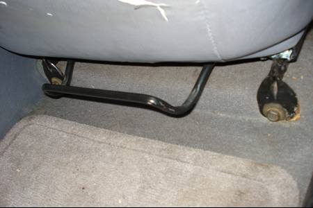
3. Move the seat rearward and remove the seat track front bolts, Fig 1 (11.28.1)
Fig 1
4. Move the seat forward and remove the seat track rear bolts, Fig 2 (11.28.2)
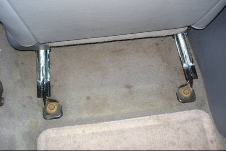
Fig 2
5. Unplug any electrical connectors, lift seat from vehicle
1. Completely raise the parking brake lever
2. Set the car in neutral
3. On 1997 models, remove the rear side trim plates and remove the retaining screws on each side
4. Remove the front and rear plugs and center console retaining screws, Fig 3 and 4 (11.25.4a, 11.25.4b)
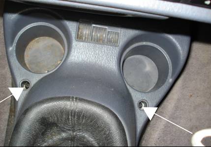
Fig 3
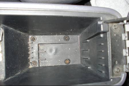
Fig 4
5. Lift the rear portion of the center console up and over the shift lever and parking brake handle and remove from vehicle Fig 5 (11.25.6 )
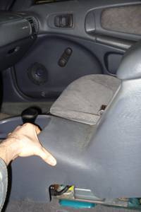
Fig 5
1. Remove the 3 attachment screws along the bottom and the one screw on the left side of the steering column cover Fig 6 (11.24.2)
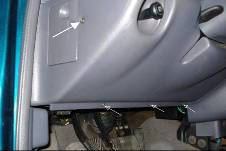
Fig 6
2. Grasp the cover and pull toward the rear to disengage the retaining clips, remove the cover
3. After the steering column cover is removed, remove the cover liner. There are two attachment screws at the upper area and the one screw on the lower left corner of the steering column cover liner Fig 7 (11.24.5)
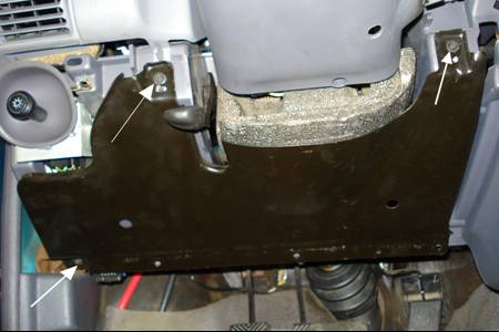
Fig 7
4. Grasp the cover and pull toward the rear to disengage the retaining clips, remove the cover liner
“This step may seem out of order, in reality this step can be done before installing the transaxle so it can be done at anytime, before, after or during. I personally did this the weekend before I actually swapped the ATX tranny out. Since the dash covers have been removed, now is an ideal time to install the pedals. There was no direct way to do this using the Haynes Repair Manual so this is simply a documented account of how I installed the pedals. There is some video that goes with this section”
1. Remove the steering column lower bracket bolts, Fig 8, it may not be possible to pull out the bracket so just let it sit (there are two bolts and two nuts with ribbed washers that hold the bracket in place along with a through-bolt that is the pivot joint for moving the steering column up and down, remove all)
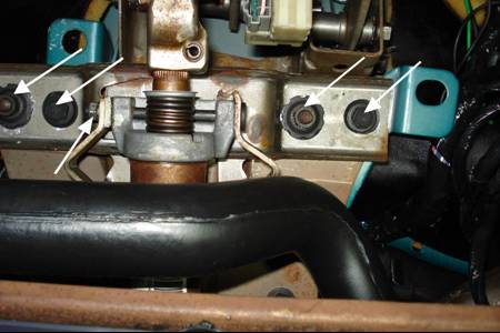
Fig 8
2. Support the steering column and remove the upper bracket nuts, Fig 9, there are two ribbed nuts that hold it in place, jostle the steering column spring loaded adjustment mechanism to get the steering column to disengage from the bolt studs BE CAREFUL steering column is heavy! Support it!
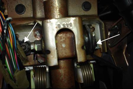
Fig 9
3. Simply jostle the steering column around to get the lower bracket out, be careful not to break any electrical components in the area
4. Remove the clip that holds the brake pedal to the brake booster piston, Fig 10
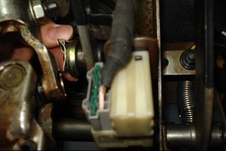
Fig 10
5. Remove the long bolt that the brake pedal pivots about, this may not be necessary but will aid in removal of the bracket
6. Remove the 6 nuts that hold the brake bracket in place, cut the black liner around the bracket and remove the bracket. This can be tricky because the bracket interferes with a welded piece of the upper dash. To make it easier look under the hood and lightly pull on the brake booster housing (the black round thing on the firewall, make sure the nuts that hold the bracket have been completely removed!) this helps disengage the bolt studs from the firewall making it easier to remove the bracket.
7. If you have cruise control, re-install the brake stop switch from the old brake bracket to the new brake/clutch bracket, this switch has the electrical plug leading to it, which can also be seen in Fig 10.
8. Install the new brake/clutch bracket
9. Re-install the 6 nuts (it may be necessary to push the brake booster housing back into the firewall) onto the new brake/clutch bracket
10. Install the clutch pedal and brake pedal onto the new brake/clutch bracket, Fig 11
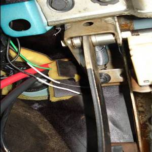
Fig 11
11. Re-install the lower steering column bracket and bolts, do not tighten
12. Re-install the upper steering column bracket nuts, it may be necessary to pushup on the steering column spring loaded adjustment mechanism to align the slots with the bolt studs to install the upper bracket
13. Tighten all bolts
14. Be sure to re-install the brake booster piston clip onto the brake pedal
15. The rest is the reverse of removal
“The pedal install took me 6 hrs, since I was doing it blindly. I would recommend doing the pedal install on a separate weekend. Essentially, take your time and be patient. You do not need to remove the steering column or brake booster; all that is necessary is to loosen them so you can get them out of the way to remove/install the pedal bracket”
The following figures show the "post facto" perspective by showing a side by side view of the ATX shifter with the MTX shifter mechanism.
1. Remove shift knob set screw and remove knob from shifter
2. Remove gearshift indicator lamp from the shift trim bezel
3. Remove the shift trim bezel screws and the bezel, Fig 12 and 13 (7B.5.10)
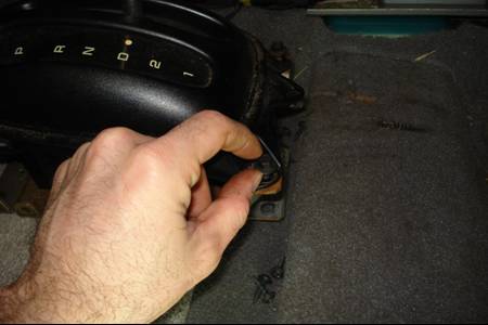
Fig 12
Fig 13
4. Use a flat-bladed screwdriver or finger and carefully pry the shift cable core end from the shift lever pin, Fig 14 (7B.5.11)
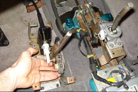
Fig 14
5. Use a small screwdriver and carefully pry the cable conduit end tabs away from the shift mechanism. Pull up and remove the cable conduit end from the groove in the shifter bracket
6. Remove the shift cable grommet plate mounting nuts, Fig 15 (7B.5.13)
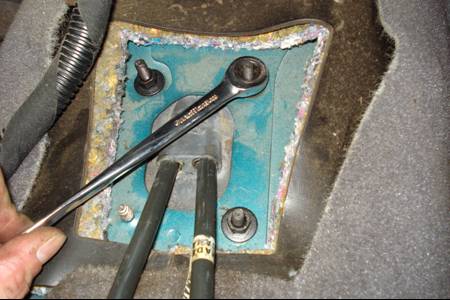
Fig 15
1. Use a small screwdriver and carefully pry out the adjuster lock on the shifter/interlock cable. Unsnap the shifter/interlock cable end fitting from the groove in the shifter bracket, Fig 16a and 16b (7B.8.9). Pull the cable out of the shifter mechanism
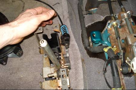
Fig 16a
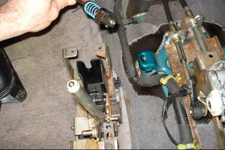
Fig 16b
2. Insert a screwdriver into the tab access hole in the lower shroud, Fig 17 (7B.8.11). Depress the lock cylinder button while rotating the lock cylinder with the key between the On and Start positions, then pull the lock cylinder from the steering column. Remove the key from the lock cylinder. (Note: Figures 12.11.5 and 12.11.6 from the Haynes Repair manual illustrate the point)
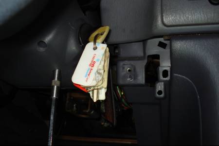
Fig 17
3. Remove the 3 lower steering column cover screws and the lower and upper steering column covers, Fig 18 (11.24.4a)
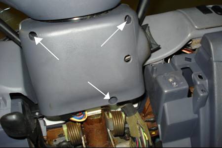
Fig 18
4. At the ignition key lock cylinder, reinsert the lock cylinder and key, position the key in the run position then squeeze the interlock cable clip and disconnect it, then pull the cable from the lock cylinder housing, Fig 19 (7B.8.13)
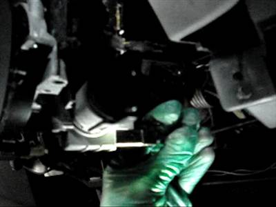
Fig 19
5. Unhook the cable retaining clip from the wiring harness and remove the interlock cable from under the center console mounting bracket and the front dash panel
6. Route the interlock cable down the steering column and down to the shift lever assembly and remove from the vehicle
1. Remove the auto-shift lever bracket base attaching nuts, Fig 20 (7B.6.7). Bolt patterns are the same for the ATX shifter as for the MTX shifter. Fig 20, points out where the nuts would be detached using the already removed ATX shifter.
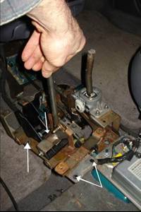
Fig 20
2. Remove the electrical connectors for the airbags from the bracket, Fig 21
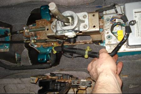
Fig 21
3. Making sure the vehicle is secure, release tension in the parking brake by releasing it. Make sure the car will not move when you release the parking brake!!! Remove the nuts holding the parking brake and the airbag system in place, Fig 22a and 22b.
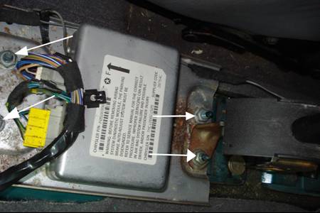
Fig 22a
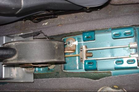
Fig 22b
4. Once the parking brake and airbag system has been moved out of the way, lift the auto-shift lever bracket off the bolt studs and remove from the vehicle, Fig 23
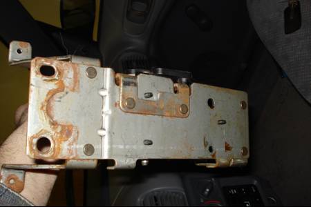
Fig 23
5. At this point go on ahead and install the manual shift lever bracket, Fig 24 (7A.3.6) then re-install the airbag system module and parking brake (shift lever bracket bolt patterns are the same between a manual and auto-shift).
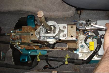
Fig 24
6. Lift parking brake and place the electrical wires back onto the newly installed manual shift lever bracket
1. Remove battery, unhook the Power Distribution Center from the battery tray, Fig 25 (7A.5.2a), remove the bolts that hold the battery tray in place. Lift tray out of engine compartment
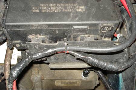
Fig 25
2. Carefully pull the Power Distribution Center up, Fig 26 (7A.5.2b), disconnect the grey and black electrical plugs from under the Power Dist. Ctr. And cover with tape to keep connectors clean
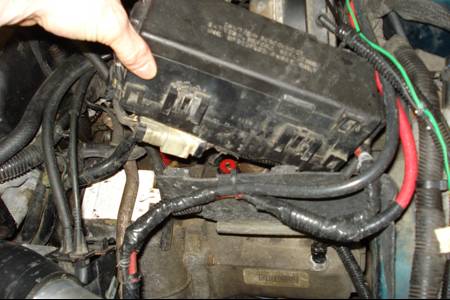
Fig 26
1. Unsnap and remove the end of the throttle pressure cable from the throttle control lever, which is located on the transaxle, Fig 27a and 27b (7B.4.5)
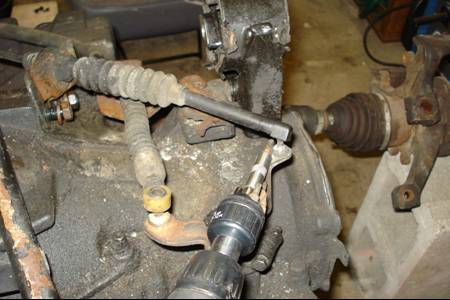
Fig 27a
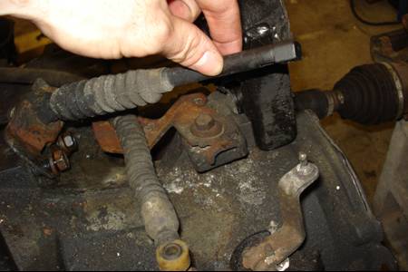
Fig 27b
2. Remove the throttle pressure control cable bracket bolt and bracket from transaxle, Fig 28a and 28b (7B.10.8)
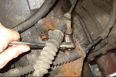
Fig 28a
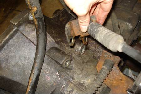
Fig 28b
3. Unsnap the cable end from the throttle linkage cam. Squeeze in on the retaining tabs and remove the cable from the mounting bracket at the throttle linkage, Fig 29a and 29b (7B.4.10), and remove cable from vehicle
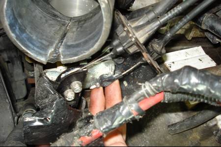
Fig 29a
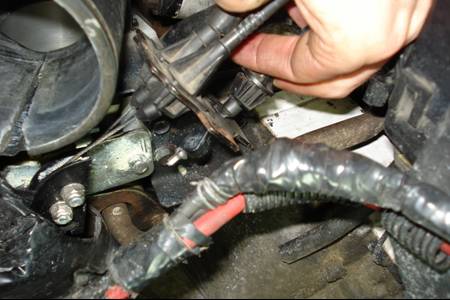
Fig 29b
1. Lift up and disconnect the shift cable from the shift lever post, Fig 30a (7B.5.5). Remove the shift cable bracket screws on the transaxle and remove shift cable from vehicle, Fig 30b and 30c.
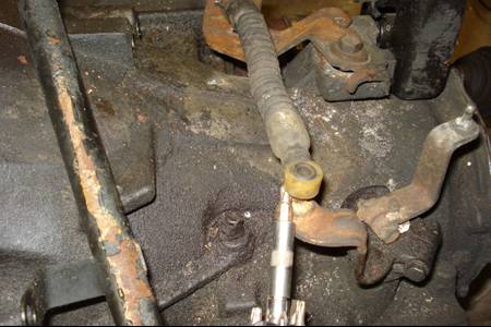
Fig 30a
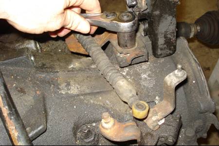
Fig 30b
Fig 30c
2. Remove the hub nut cotter pin and discard it on wheel hub, discard it and use a new one for reassembly, remove the driveaxle hub nut lock and spring washer, Fig 31 (8.8.2a and 8.8.2b)

Fig 31
3. Set the parking brake, loosen the hub/driveaxle nut with a large socket and breaker bar. Do not remove nut only loosen it. Perform this operation for both front wheels, Fig 32 (8.8.3).
Fig 32
4. Loosen the front wheel lug nuts. Raise the front of vehicle (30 inches) and support it securely on jackstands, make sure the rear tires are SECURED!, raise the rear end as to minimize front end rise angle, remove both front wheels
5. Remove both hub/driveaxle nuts
6. Working under the vehicle, remove the shift cable retainer plate, Fig 33 and 34 (7B.5.15)
Fig 33
Fig 34
7. Carefully remove the shift cable out through the underbody floor opening while unfolding the cable retainer clips
8. Remove the shift cable assembly from the vehicle
1. Remove the brake caliper from the rotor, do this by removing the two bolts securing the brake caliper to the wheel housing, Fig 35, carefully suspend the caliper+pads out of the way as to not put tension on the brake line, remove the rotor from the wheel hub (do this on both front sides of the vehicle)

Fig 35
2. Remove the nut securing the tie-rod end stud to the steering knuckle, tap the tie rod end stud with a hammer to loosen it from the knuckle (put the nut back onto the end of the tie rod stud, this will help keep you from destroying threads if you miss while tapping), once out of the knuckle move the tie rod out of the way of the hub, it is not necessary to remove the tie-rod from the steering assembly, if it won’t tap out a puller/pusher tool may be required, Fig 36 (10.16.4 and 10.16.5)
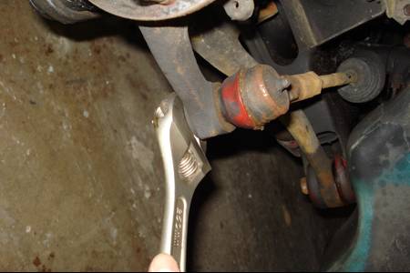
Fig 36
3. Remove the bolt and nut securing the balljoint to the steering knuckle, then pry the lower control arm down to separate the components
4. To loosen the driveaxle from the hub splines, tap the end of the driveaxle with a soft-faced hammer (8.8.8). If the driveaxle is stuck in the hub splines and won’t move, it may be necessary to push it from the hub with a puller
5. Pullout on the steering knuckle and detach the driveaxle from the hub (8.8.9). Suspend the outer end of the driveaxle on a bungee cord or piece of wire
6. To remove the right (passenger’s side) driveaxle, position the pry-bar against the inner tripot joint and carefully pry the joint off the transaxle side gear and retaining clip, Fig 37 (8.8.11). Pry straight out! Do not stress the axle assembly
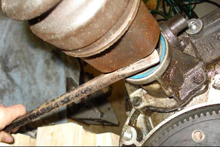
Fig 37
7. To remove the left (driver’s side) driveaxle. Position a pry-bar against the metal lip and carefully pry out the transaxle side gear, Fig 38 and 39 (8.8.12a and 8.8.12b). Pry straight out! Do not stress the axle assembly
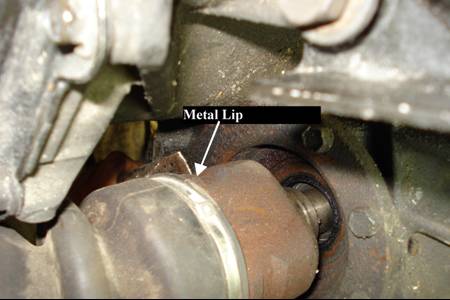
Fig 38
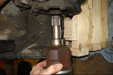
Fig 39
“Step 7 in this section is a pain in the butt (try not to get too angry), it’s not as easy to remove the driver’s side axle on an automatic transaxle. On the automatic you will not be able to get a pry-bar all the way in the back of the axle. There is a very narrow "Metal lip" that you will have to pry on. The lip is located just before the rubber boot.”
1. Remove the dipstick tube (if not done so already)
2. Disconnect the transaxle cooler lines at the transaxle, Fig 40 (7B.10.10). Plug ends to avoid contamination
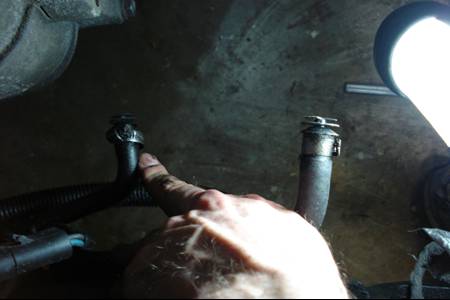
Fig 40
3. Disconnect the electrical connectors for neutral safety/backup lamp switch, torque converter lockup switch and speed sensor.
4. Remove the upper bellhousing bolts and the starter motor upper bolt, Fig 41, 42 and 43 (7B.10.11)
Fig 41
Fig 42
Fig 43
5. Position a container under transaxle. Drain the transaxle fluid, remove drain plug and let drain until it stops (about 4 qts) some fluid will remain in torque converter, which is fine. If a drain plug does not exist then loosen all the bolts on the transmission pan, tap the pan to break the seal and let the fluid drain through the seal. Re-attach the pan and drain plug.
6. Carefully support the engine from above or with a floor jack pressed against the oil pan with a piece of wood between the oil pan and jack, this is done to avoid damaging or crushing the oil pan
7. Support the transaxle with a transmission jack, if available, or with a floor jack. Safety chains will help steady the transaxle on the jack
8. Remove any exhaust components which will interfere with transaxle removal
1. Remove the transaxle to rear lateral support bracket, Fig 44 (7B.10.18)
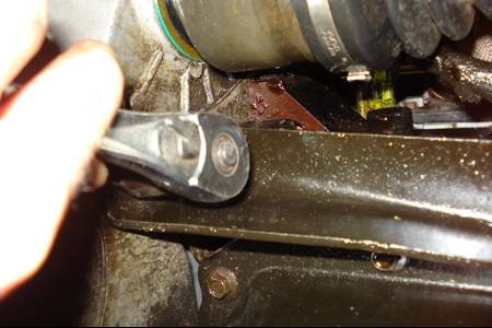
Fig 44
2. Remove the engine front mount insulator through bolt, Fig 45a, mounting bolts, Fig 45b, and mass damper, Fig 46. Remove the mount insulator (2A.19.9a)
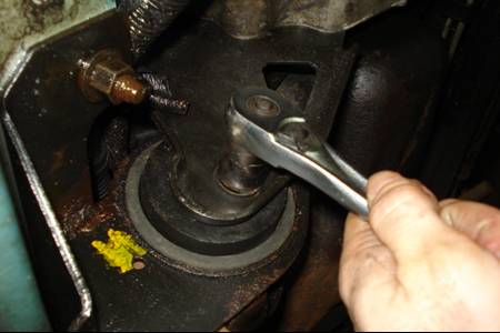
Fig 45a
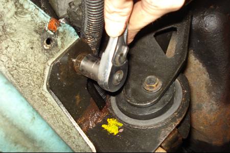
Fig 45b
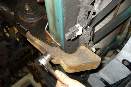
Fig 46
3. Remove the front motor mount bolts, Fig 47, and remove the mount
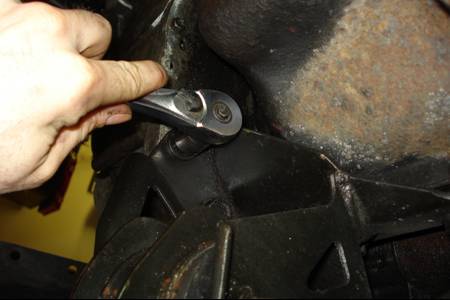
Fig 47
4. On models so equipped, remove the structural collar from the oil pan and transaxle, Fig 48
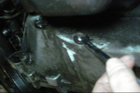
Fig 48
5. Remove the starter motor lower bolt (if not already done so) and ground strap. Simpy move the starter motor back and out of the bellhousing
6. Remove the dust shield on the damper (accessory) pulley side
7. Remove any remaining chassis or suspension components which will interfere with the transaxle removal
8. Remove the four driveplate-to-torque converter bolts. Rotate the engine crankshaft by turning the damper pulley clockwise to expose the bolts (7B.10.26a). Remove all four bolts, Fig 49 (7B.10.26b)
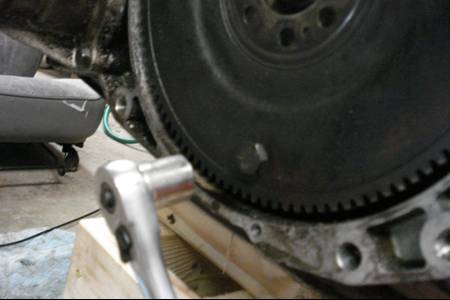
Fig 49
9. Remove the transaxle mount through-bolt, Fig 50 (7B.9.3a and 7B.9.3b). Continue to support the transaxle with a jack (you may need to jack up on the transaxle to release pressure on the mount), It is not necessary to remove the mount from the transaxle, but you may do so to make overall transaxle removal easier.
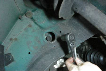
Fig 50
10. Remove the upper rear lateral transaxle-to-engine bolts and bracket
11. Make a final check that all wires and hoses have been disconnected from the transaxle, then move the transaxle and jack toward the side of the vehicle until the transaxle is clear of the engine locating dowels. Make sure you keep the transaxle level as you do this. NOTE: As soon as the transaxle clears the engine, attach a small C-clamp to hold the torque converter to the transaxle housing during the remainder of the removal procedure
12. Lower the transaxle and remove it from under the vehicle
WARNING! I would not recommend removing the transaxle using a floor jack expecially the way I used it in the video. It is indeed very dangerous to use a floor jack especially without the aid of safety chains. A shim system is also a very dangerous approach. Primary dangers are the floor jack gets top heavy and tips over or the floor jack prematurely rolls off of the shims. These two senarios can cause personal injury or damage components to the car. Once again, I showed this experience of mine as a reminder to make sure you rent or put thought into getting a transmission jack prior to a transmission/transaxle removal. I did not and this is the consequence I ended up with. It was a very time consuming, nerve-racking experience. One in which I will never experience again because I will be sure to rent a transmission jack ahead of time.
WARNING! I would not recommend removing the transaxle using a floor jack expecially the way I used it in the video. It is indeed very dangerous to use a floor jack especially without the aid of safety chains. A shim system is also a very dangerous approach. Primary dangers are the floor jack gets top heavy and tips over or the floor jack prematurely rolls off of the shims. These two senarios can cause personal injury or damage components to the car. Once again, I showed this experience of mine as a reminder to make sure you rent or put thought into getting a transmission jack prior to a transmission/transaxle removal. I did not and this is the consequence I ended up with. It was a very time consuming, nerve-racking experience. One in which I will never experience again because I will be sure to rent a transmission jack ahead of time.
1. Remove the bolts that secure the flywheel to the crankshaft, Fig 51 (2A.17.4). Wedge a screwdriver in the flywheel to hold it in place, specialty tools are also available at autoparts stores
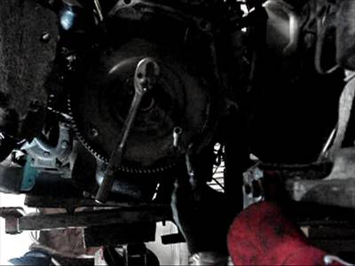
Fig 51
2. Remove flywheel, its really not heavy but support it anyway (2A.17.5)
“This step is not necessary to do the swap, but if it has been leaking replace it! You don’t need oil on your newly installed clutch. I think it’s a good idea since rear main oil seals are very cheap to buy and since you are doing all the work to get there you might as well replace it”
1. Pry the old seal with a 3/16’’ flat blade screwdriver (2A.18.2), DO NOT SCRATCH the machined crankshaft seal bore surface in the block.
2. Thoroughly clean the bore surface with acetone or lacquer, DO NOT LUBRICATE the lip of the new seal when installing
3. Drive in the new seal onto the crankshaft using the automatic flywheel. Do this by placing the rear main oil seal in position then put the flywheel back on and tighten a few bolts to press in the seal, make sure “this side out” is facing out, DO NOT DRIVE SEAL IN PAST FLUSH only drive the seal in far enough to be flush with the outer surface of the block its okay to drive it in further than the inner surface of the crank in fact that is recommended, otherwise the seal will rub against the flywheel which is undesirable, Fig 52 (2A.18.4)
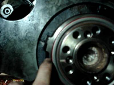
Fig 52
MTX INSTALLATION
TABLE OF CONTENTS MTX INSTALL
1. Position driveplate against the crankshaft, Fig 53. Before installing the bolts, apply thread locking compound to the threads
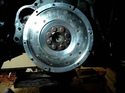
Fig 53
2. Wedge screwdriver in gear teeth on driveplate to hold in place while tightening bolts or use a ratchet on the damper pulley bolt to hold the crankshaft in place, torque spec - 70 ft-lbs
1. Wipe driveplate outer surface with brake cleaner, make sure there is no oil or grease
2. Position the clutch disc against the driveplate and center it (8.4.17a). While holding the clutch disc, install the pressure plate against the driveplate, Fig 54 (8.4.17b)
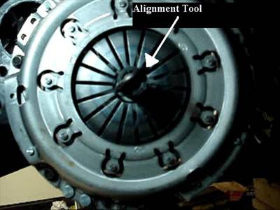
Fig 54
3. Hold the pressure plate in place and install the mounting bolts and finger tighten them (8.4.18a). Install an alignment tool (8.4.18b), make sure alignment tool is recessed into the crankshaft
4. Tighten the pressure plate in a criss-cross pattern until snug, then torque - 250 inch-lbs
For a more indepth perspective for the clutch installation try using <www.allpar.com/neon/clutch.html
1. Clean and wipe down spline and input shaft on manual transaxle
2. Using high temp grease lubricate the inner groove of the release bearing, put a light coat of grease on the release lever contact areas, and input shaft splines and bearing retainer (8.5.7a and 8.5.7b)
3. Install release bearing onto the input shaft (8.5.5)
4. Install the release lever fingers onto the release bearing and onto the pivot ball (8.5.9). (NOTE: do not lubricate pivot ball for it is made out of Teflon). Snap the lever into place on the pivot ball. Make sure it is properly seated and that the spring clip is inserted through the release lever slot
5. Replace driveaxle seals on transaxle, carefully pry seal out with a screwdriver, Fig 55, clean mounting surfaces, lubricate the lip of the new seal with multi-purpose grease, install onto the mounting surface (use a round pipe to install the seal squarely, 7A.7.4 and 7A.7.6)
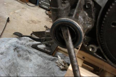
Fig 55
“This is not as easy as it looks, prying out the old axle seal is tough and if there is a tool for it rent it! Figure 55 is using the ATX transaxle as an example of prying out the old seal, obviously you will be replacing the seal on the MTX transaxle.”
1. With transaxle secured to the jack, raise it into position and carefully slide it forward, engaging the input shaft with the clutch splines. Do not use excessive force readjust transaxle angles so the splines properly engage with the clutch
2. Install the left transaxle mount on transaxle (if not already done so). Install transaxle mount thru-bolt (7A.5.28), torque - 40 ft-lbs
3. Install the starter motor, the ground strap!, and the lower bolt (people forget the ground strap which can be a huge disappointment the first time you try to start). Do not tighten the bolt at this time.
4. Install the structural collar, front motor mount bracket, motor mount bolts and through bolt, torque - 45 ft-lbs
5. Install the transaxle to rear lateral support bracket (7A.5.22), torque - 40 ft-lbs
6. Install the transaxle bobble strut bracket on the transaxle and install the torque damper or bobble strut, Fig 56 (7A.5.20), torque - 40 ft-lbs
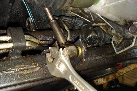
Fig 56
1. Installation is the reverse of removal (use the ATX removal instructions to re-install)
2. Apply a bead of multi-purpose grease around the splines of the inner tripot
3. When installing the driveaxle, hold the driveaxle straight out push it in sharply to seat the driveaxle snap ring into the groove in the transaxle side gear
4. Perform the rest of the installation using the reverse of the instructions from the ATX removal instructions, don’t worry about lowering the car at this point
1. Install any exhaust components that were removed
2. Remove any jacks or wood blocks from transaxle
3. Install bellhousing upper bolts, torque - 70 ft-lbs
4. Install the starter motor upper bolt and tighten both the upper and lower bolt, torque - 40 ft-lbs
5. Install the intake manifold support bracket and dust shields (if equipped)
6. Install the accelerator cable shield (if equipped)
7. Install the shift cable mounting bracket (if not already done so), torque - 21 ft-lbs
1. Within the engine compartment, using a slight twisting motion insert the self-adjusting end of the clutch cable through the grommet in the firewall and the clutch bracket, Fig 57 (8.3.6)
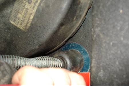
Fig 57
2. Seat the cylindrical part of the grommet into the firewall opening and clutch bracket. Make sure the self-adjuster is firmly seated against the clutch bracket to ensure the adjuster will function properly
3. Connect the clutch cable end onto the up stop/spacer and install the spacer onto the clutch pedal pivot pin. Install the clip and make sure its properly seated (8.3.5a, 8.3.5b and 8.3.5c)
4. Within the engine compartment, using slight pressure, pull the clutch cable end to draw the cable taut. Push the cable housing toward the firewall with less than 25 lbs of pressure. The cable housing should move about 1 inch this indicates proper adjustment. If this does not adjust, determine if the mechanism is properly seated on the bracket
5. Guide the cable through the slot in the bellhousing and connect it to the release lever seating the cupped washer securely in the release lever tangs
6. Pullback on the clutch cable housing and insert it into the bellhousing, Fig 58a and 58b (8.3.4)
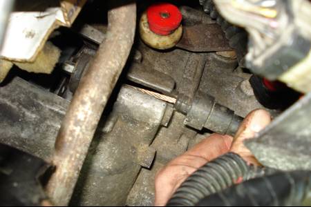
Fig 58a
Fig 58b
7. Install the clutch cable inspection cover onto the bellhousing (8.3.3)
1. Using new booger bushings install the selector cable onto the select lever, Fig 59 (7A.2.5)
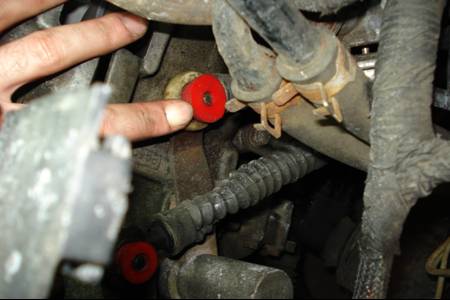
Fig 59
2. Using new booger bushing install the crossover cable from the crossover lever, Fig 60 (7A.2.6)
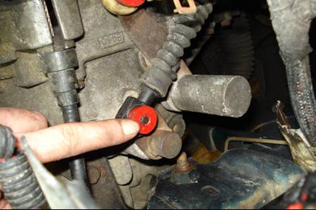
Fig 60
3. Install cables on cable bracket, install new retaining clips onto the bracket, Fig 61 (7A.2.7)
Fig 61
1. Beneath the car install the floor pan grommet (7A.2.13), cables and install mounting nuts (7A.2.9)
2. Using new booger bushings, install shifter cables onto the shift lever, Fig 62 (7A.2.11), install new cable retaining clips at all location and make sure they are properly seated, Fig 63 (7A.2.10)
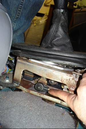
Fig 62
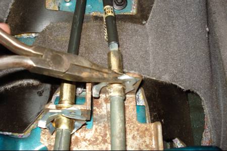
Fig 63
1. Loosen the crossover cable adjusting screw, Fig 64 (7A.2.18)
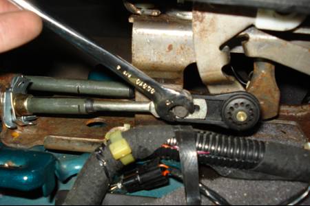
Fig 64
2. Align the hole in the crossover lever with the hole in the transaxle raised boss. Insert a 1/4 inch drill bit through the lever and into the raised boss, Fig 65 (7A.2.19). Make sure the drill bit goes into the transaxle hole at least ˝ inch.
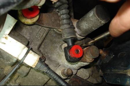
Fig 65
3. Place the shifter lever in the neutral position (allow the shifter to self-center in this postion)
4. Tighten the crossover cable adjusting screw, torque - 70 in-lbs. The shift lever must stay in the self-centered position while tightening the screw
5. Remove the Ľ inch drill bit from the lever and transaxle
6. Shift the transaxle into all gear positions to make sure the cable is functioning properly, readjust as necessary
1. Connect the electrical connector for the speed sensor, Fig 66 (6.3.48)
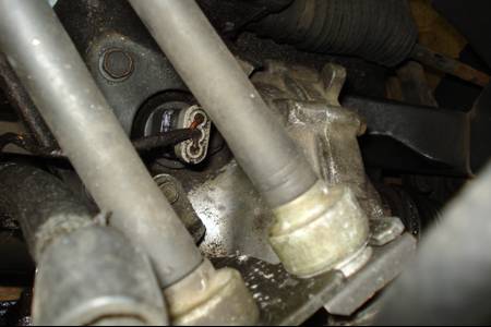
Fig 66
2. Move the Power Distribution Center back into its holding bracket
3. Install the batter tray (5 bolts), the battery and attach the battery cables
4. Fill the transaxle with fluid. There is no dipstick use the rubber plug on the side of the transaxle to check fluid level. Start filling the transaxle with fluid using a funnel, when fluid starts coming out of the hole the transaxle is full. Plug the hole back up with the rubber plug.
MTX transaxle fluid can be purchased from <www.modernperformance.com
1. Install the front motor mount (if not done so already), dash covers, center console covers, driver’s seat and all other removed components, if you need a guide use the reverse of removal from the “ATX removal” section
1. Place the wheels back onto the hubs, finger tighten the lug nuts
2. Lower the vehicle, once lowered tighten the lug nuts, torque - 100 ft-lbs
3. Tighten the driveaxle/hub nut, torque - 135 ft-lbs
4. Install the cap and cotter pin on driveaxle hub
“Since your car was once an automatic there are a few electrical issues. Within the internals of both the ATX and MTX PCM there is a link between the park/neutral safety start switch and the cruise control. This is not entirely clear when looking at a circuitry diagram, which makes it appear the two are completely independant of one another."
"There are 3 wires that were part of the neutral/park safety switch they were a BRN/YELL, WHT, and a VIO/BLK wire. The WHT and VIO/BLK wires simply plug into the reverse lamp switch. The BRN/YEL wire is the neutral/park safety switch.”
1. Cut off the neutral/park safety plug that holds the 3 wires and expose the wires, splice with longer wire if the wires are not long enough (just remember which is which if you don’t have the same color wire, label if need be)
2. If you do not have cruise control simply ground the BRN/YELL wire to the grounding point on the frame near the battery tray (there are two grounding points, either will suffice)
3. The WHT and VIO/BLK wire need to be plugged into the reverse lamp switch (orientation doesn’t matter), either go to a junkyard to get a plug from a manual neon and splice in the wires or just hard wire the wires to the switch and cover it with electrical tape
4. If you have cruise control then the BRN/YEL wire should be spliced in with the clutch pedal switch and then grounded to one of the grounding points on the frame in front of the battery tray. This is because the BRN/YEL wire must be grounded to start the car but ungrounded in order to use cruise control
“There is no need to splice in the YEL wire with the clutch pedal switch. Once again if you splice in the BRN/YEL wire (step 4) into the clutch pedal that is all that will be necessary to start the car by fully engaging the clutch and be able to use cruise control, therefore it is okay for the YEL wire to be shorted/bypassed as it has already been configured for an automatic transaxle.”
"Recently, I have tested both an ATX and MTX PCM in my car. The electrical configuration and procedure outlined in this section is indeed valid for both PCMs. Make note the MTX PCM I used was defective from the distributor and this was confirmed by the distributor. The PCM threw code 35 which has to do with activating the fan for the radiator. Keep in mind this was a defect in the PCM itself! hence this was the reason why I got the PCM for $0.99 on ebay. OTHERWISE, THE MTX PCM WORKED FINE AND THAT THE ELECTRICAL CONFIGURATION I CHOSE WITH THE BRN/YEL WIRE HAD NOTHING TO DO WITH CAUSING CODE 35. Three subsequent videos have been added, which show road test of both PCMs."
